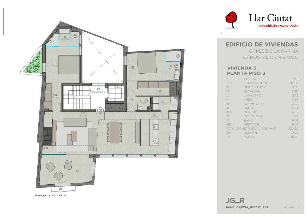
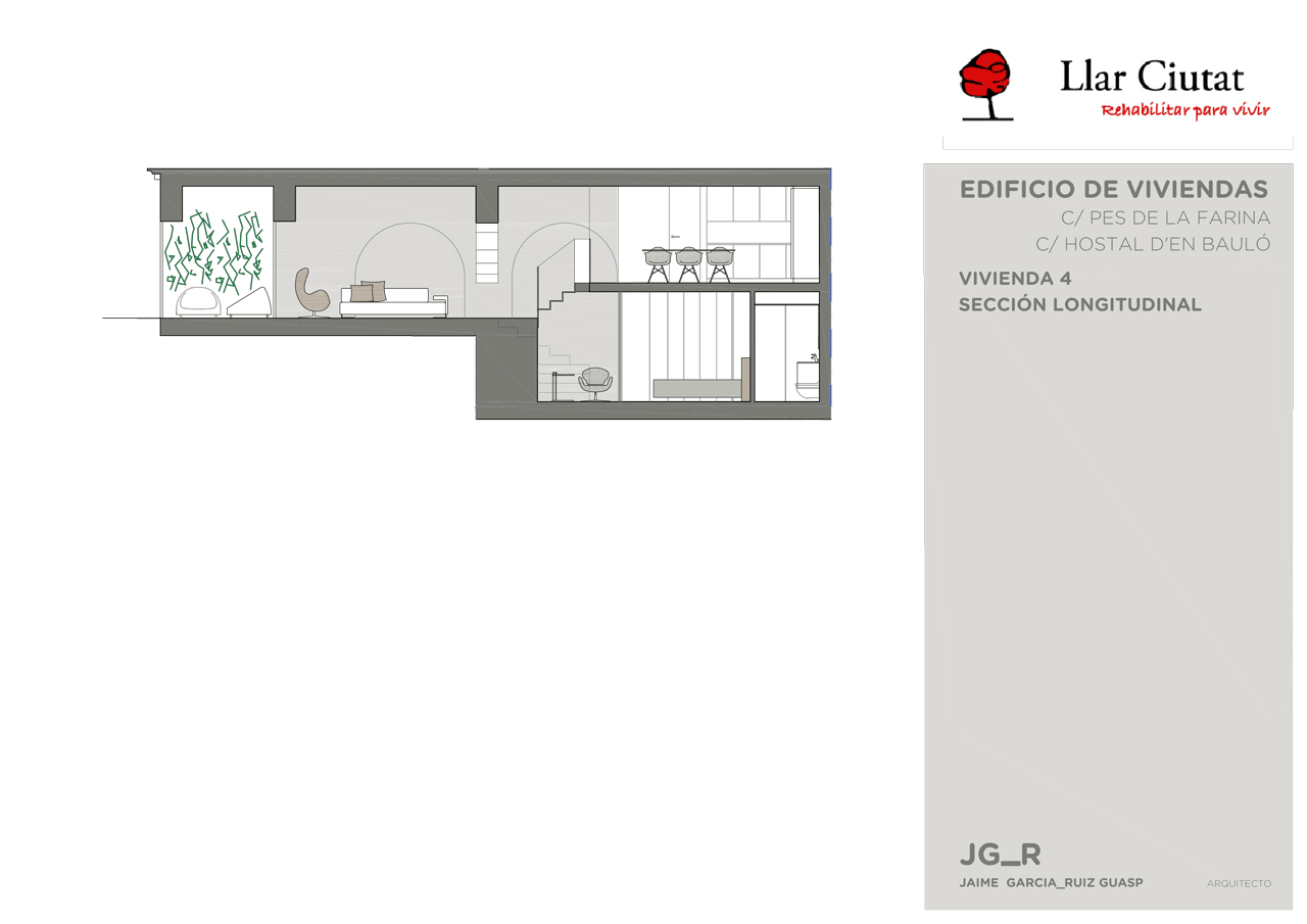
RENOVATION OF RESIDENTIAL BUILDING BETWEEN ADJOINING PROPERTIES, C/ PES DE LA FARINA 17, C/HOSTAL D'EN BAULO 1 & 3 . PALMA
The building specifications document includes the following sections:
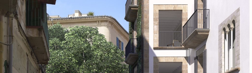
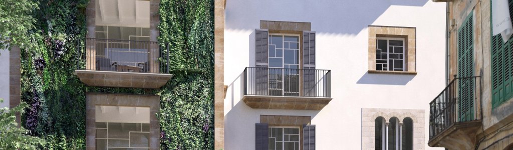
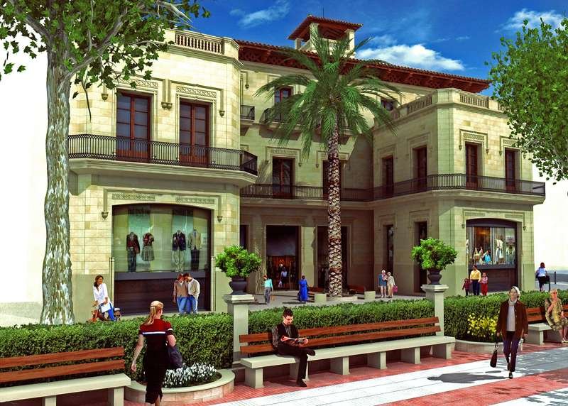
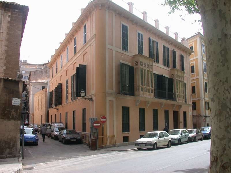
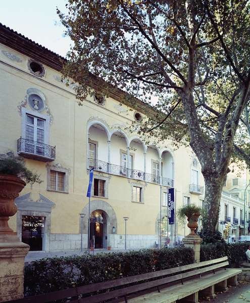
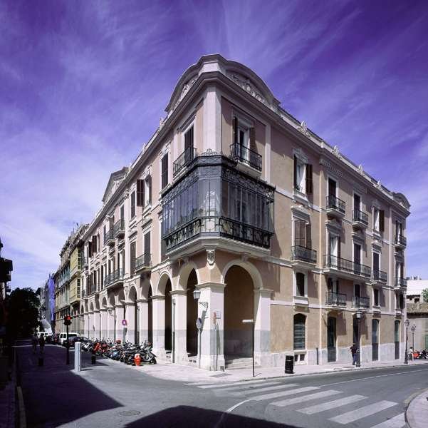
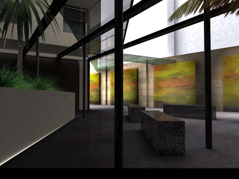
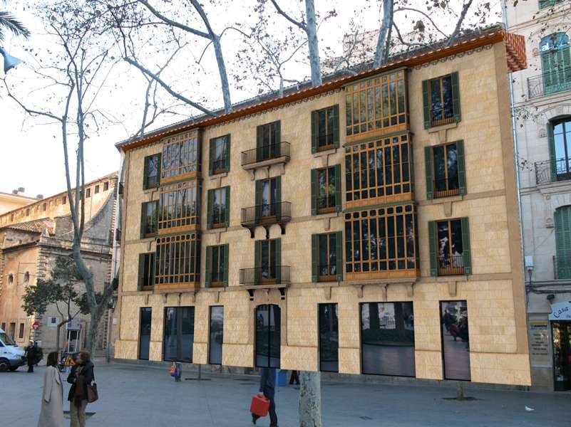
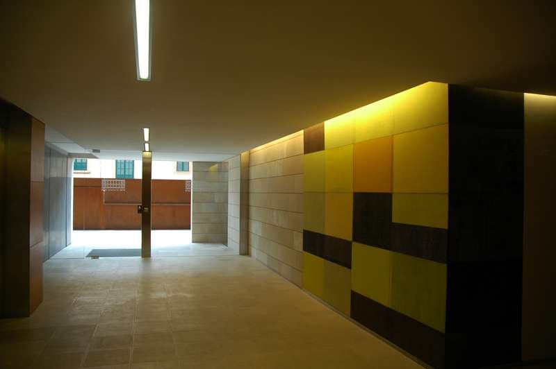
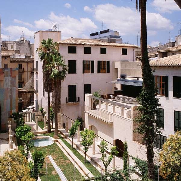
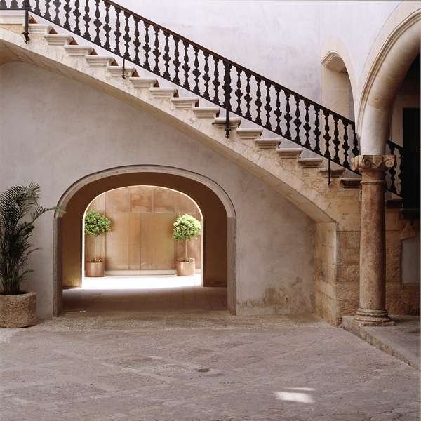
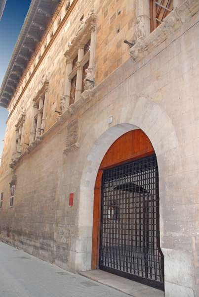
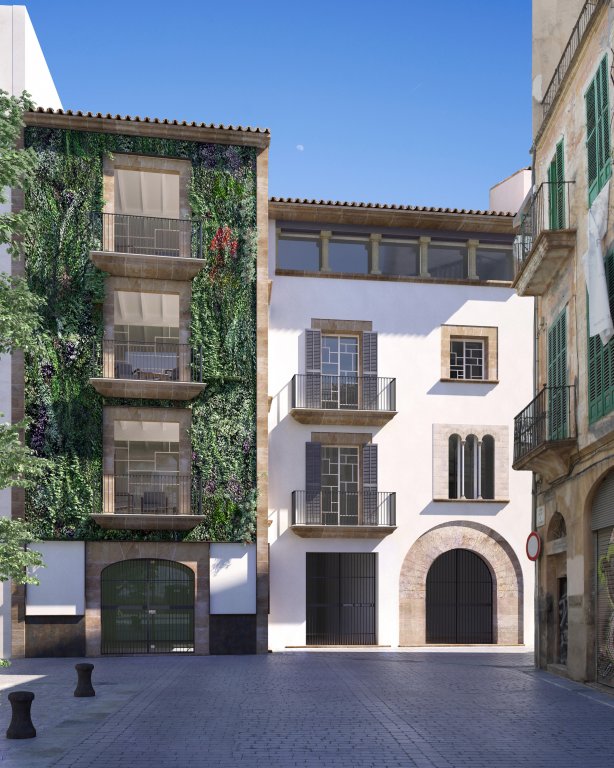
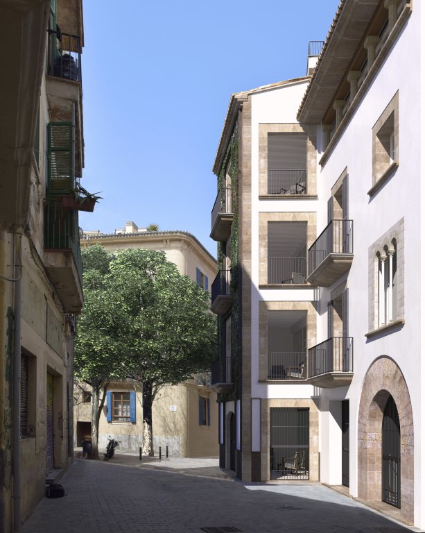
Ca'n Bauló is a medieval building located in the old neighborhood of "Sa Gerreria", which was part of the Old Town of Palma. It was declared a heritage property in 1964 due to its historical and artistic importance. During the Middle Ages it was one of the most artisan and relevant neighborhoods of the Ciutat where the works of potters, blacksmiths and merchants were developed.
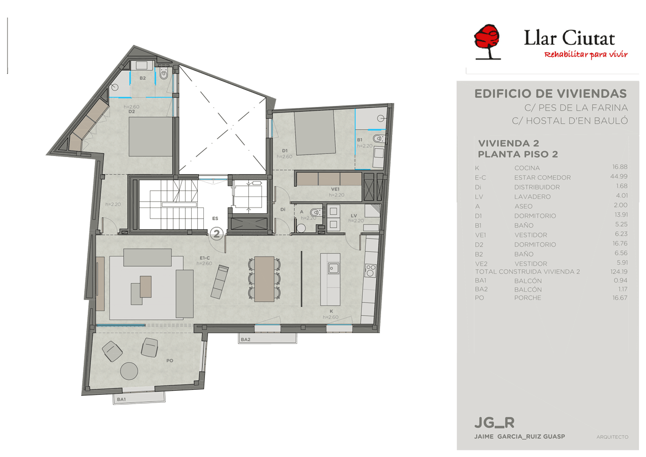
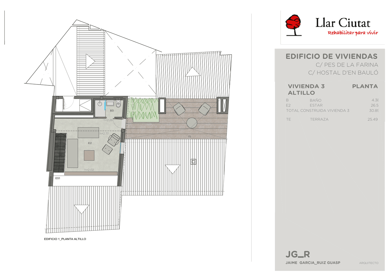
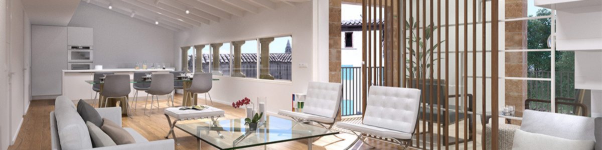
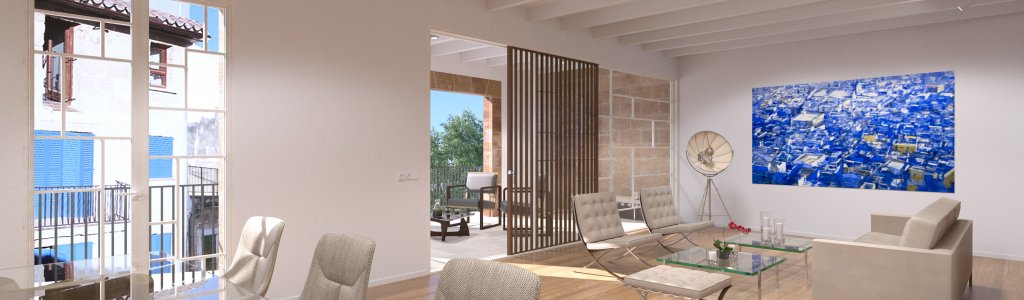
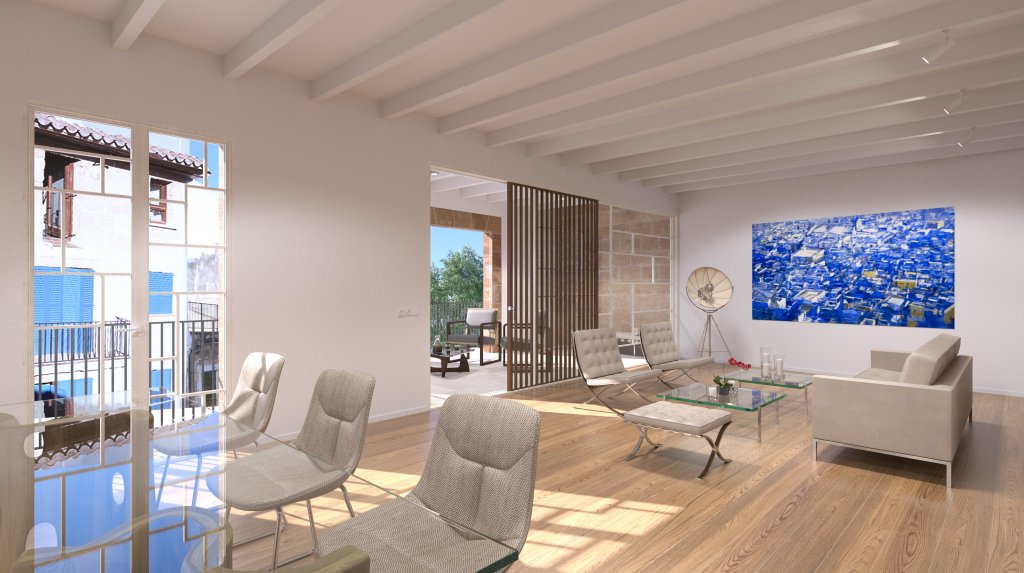
Ca'n Bauló is a building located in the heart of the city of Palma de Mallorca. It will have four magnificent quality homes and made with materials of superb quality. The selection criteria for the finishes will be design, comfort and durability.
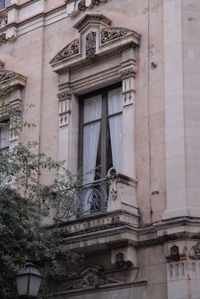
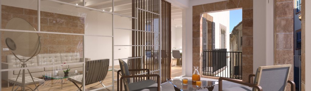
This historical building of great architectural and artistic beauty stands out mainly for its Medieval, Renaissance and early 19th century elements, for its Romanesque arch and for its spectacular Gothic window of great architectural value. Its various pointed arches and half-point arches in different areas of the building will complement a spectacular rebirth of a forgotten past.


BUILDING SPECIFICATIONS
RENOVATION OF RESIDENTIAL BUILDING BETWEEN ADJOINING PROPERTIES, C/ PES DE LA FARINA 17, C/HOSTAL D'EN BAULO 1 & 3 . PALMA
The building specifications document includes the following sections:
Given the features of the land, the building foundations will be deep with individual micropile cap and strip footing under base walls linked to one another by tie beams.
The load-bearing structure of the building is constructed on a metal pillar base.
The horizontal structure for the first bay and sloping roofs uses one-way prefabricated slab beams measuring 10x20 cm with a 56 cm separation between the axis and flat ceramic top slab with a compression layer of 5 cm and ME Ø5 20x20 reinforcement framework supported by porticoes comprising metal pillars and beams. The remaining framework will be metal joists, with Porexpan beam filling and a 5 cm compression layer with ME Ø5 20x20 reinforcement framework or 20 cm reinforced concrete slab with a ME Ø10 15x15 upper and lower base framework supported by porticoes made from metal pillars and beams.
The staircase ramp is planned to be sloping reinforced concrete slabs. Except for stairs inside homes that will be metal.
The determining technical parameters when selecting the façade system were: compliance with sound regulations CTE-DB-HR and limiting energy use CTE-DB-HE, as well as using a system that ensured correct water-proofing as per CTE-DB-HS protection against damp.
The building roof comprises flat and sloping roofs.
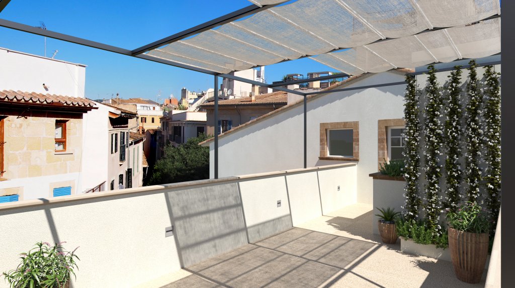
The flat roof has no vapour barrier, a 10 cm layer base of light concrete to form slopes between 1 and 5%, a standardisation layer of 2 cm thickness comprising cement mortar, 8 cm thick rigid extruded polystyrene sheets, a 100 g/m² glass fibre felt separation layer and water-proofing via a single layer non-adhesive solution type PN-1 with a Polyvinyl chloride (PVC-P) sheet, a 100 g/m² geotextile synthetic felt separation layer, a 2 cm thick standardisation layer of cement mortar and a porcelain stoneware non-slip floor 30 x 30 in communal areas, whilst the private terrace will be finished in bush-hammered natural limestone 60×30×3 cm or similar.
The sloping roof comprises an insulation layer of 8 cm-thick projected polyurethane over a framework and covered with half-mortared curved ceramic roof tiles.
The new full-building outside wall will be double-layer comprising: a ½ foot exterior layer of hollow brick finished on the outer face with lime mortar, a heat cavity and rockwool insulation layer 6 cm thick, and an interior double hollow breeze block layer 6.5 cm thick with a plasterwork coat finish.
The current masonry walls on the ground and first floor will be externally finished with lime mortar whilst the interior will have a new double breeze block layer 6.5 cm thick with a plasterwork finish.
The openings in the exterior wall shall be framed with Gladent sandstone pieces or similar.
The current arcade work on the façade and inside the ground floor shall be recovered and restored, as well as the triple arch double column 'coronella' window.
The walls that touch the ground on the ground floor shall be 30 cm concrete walls. A high-density polyethylene sheet for water-proofing shall be inserted between the concrete and the ground.
Floors that sit on the ground on the ground floor shall be 20 cm concrete flagstones on a sand and stone bed on top of the natural ground. A high-density polyethylene sheet for water-proofing shall be inserted between the concrete and the sand.
Exterior joinery shall be matt white lacquered spruce in acrylic polyurethane material with a classification of A1/E1/V1 as per sections and openings shown in the corresponding specifications plan.
Exterior windows: Pre-frame in spruce, Frame 7x7 cm, and overlapping spruce window leaves, insignis pine interior flashing 7x1.4 cm. Balcony: Lower strip ~20 cm; rails 9.5x7 cm for single window per leaf; Window: Rails 9.5x7 cm for single window per leaf; Fittings: Double rubber for heat and sound insulation, tilt-and-turn fittings with AGB mechanisms, double spigot hinge plate.
Exterior sliding windows: Spruce pre-frame, Frame 17x4.5 cm and slide and lift window leaves in spruce (1 fixed leaf + 1 slide and lift leaf); insignis pine interior flashing 7x1.4 cm; Balcony: Lower strip ~20 cm; rails 9.5x7 cm for single window per leaf; Fittings: Double rubber for heat and sound insulation, slide-and-lift fittings with AGB mechanisms or similar.
The glass will be double glazed with a thickness of 4/12/4 mm.
There will be Majorcan-style exterior shutters with wooden slats painted grey NCS S5005-G20Y. Iroko wood shutter panes with closed round slats. Balcony: Lower strip ~20 cm; rails 7x4 cm; Window: ~9 cm lower rail + 7x4 cm rails; Fittings: cadmium belt and catches, brass hinges and tips.
The determining technical parameters when selecting the partition system were: compliance with sound regulations CTE-DB-HR and what is set out in DB-SI for elements separating the property.
The separations for the staircase, homes and fire sectors on floors above ground, in order to comply with what is set out in DB-SI and achieve greater heat-sound comfort, shall have a double H-6 7 cm-thick brick wall on 10 mm-thick elasticised expanded polystyrene, 5 cm air cavity with a sheet of intermediate Isover Acustiline 40 mm-thick rockwool or similar with a plasterwork finish on both sides.
The interior party walls will generally have a double hollow breeze block base.
The interior joinery will generally be matt white lacquered spruce in acrylic polyurethane material, with smooth doors, wardrobe doors, fittings and on 7 cm frames in the same wood on a spruce sub-frame.
Smooth Reinforced Entry Door: Spruce sub-frame, 10x4.5 cm Frame and smooth single leaf reinforced door with a hollow spruce structure with 3 mm MDF + 0.8 mm galvanised plate + 5 mm MDF either side. Insignis pine flashing 7x1.4 cm. Fittings: Rubber on frame for sound-proofing, safety hinges, 3-point MCM 701 lock with a stainless steel finish or similar, interior handle, exterior knob and spyhole.
Smooth interior doors with glass panels on top: Spruce sub-frame, 10x4.5 cm Frame and smooth single leaf door + glass panel with a hollow spruce structure with 5 mm MDF either side. Insignis pine flashing 7x1.4 cm. Fittings: Rubber in frame for sound-proofing, hinges, silent lock MCM 1719 stainless steel finish or similar, handle with stainless steel finish.
Sliding smooth interior doors: Spruce sub-frame, 10x4.5 cm Frame and smooth single leaf door + glass panel with a hollow spruce structure with 5 mm MDF + Antaris ply or similar either side. Insignis pine flashing 7x1.4 cm. Fittings: Ducasse DN 80 hidden sliding mechanism, ashtray-type handles finished in stainless steel.
Wardrobes: 19 mm MDF door, insignis pine flashing and tips 7x1.4 cm. Interiors in melamine modules with separate shelf and rail, hidden spruce skirting. Fittings: Concealed hinges with cushioned closing, railing, knob handles or push mechanisms.
Interior joinery materials specs
The stairs shall have metal bar railings with steel handrails anchored to the walls in accordance with regulations.
Grilles shall be installed with flat metal plates and iron bars to paint on the doors leading to the hallway, ground floor porches and the garage. The balcony railing shall be steel flat metal to paint.
The finishes have been selected based on comfort and durability.
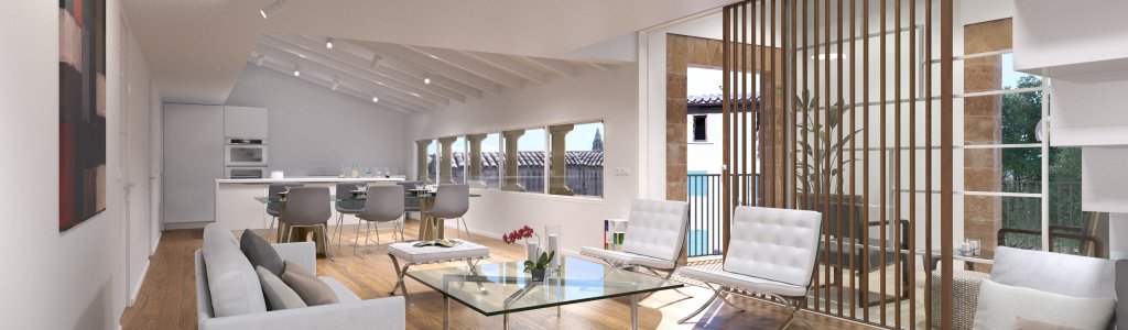
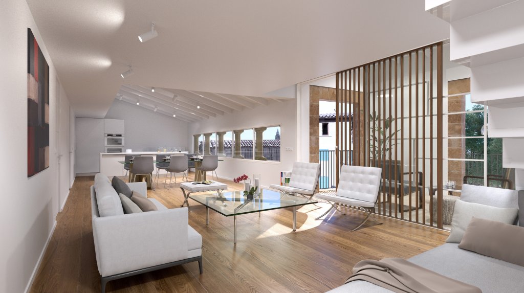
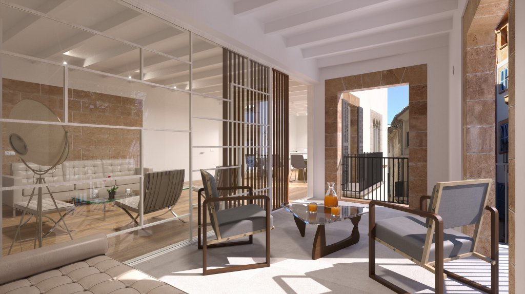
The interior floors of the homes will be weathered white oak parquet (Energía Natural by Joan Loa), except in the bathrooms and WCs, which will be finished in large porcelain tiles Coverlam Titan cement 5.6 mm thick or similar, including the shower flooring. The porches and terraces in the homes will have natural bush-hammered limestone tiles 60x30x3 cm or similar.
Parquet Energía natural Coverlam Titan tiles
The garage floor shall be continuous uniform non-slip cement paving.
The communal areas in the entrance hall, outdoor stairs and on private balconies will be natural bush-hammered limestone 60x30x3 cm, whilst the indoor stairs will use the same material with a honed finish.
The bathroom wall will be in large porcelain tile Coverlam Titan cement 5.6 mm thick or similar on a Portland cement bed, sections as per details, whilst the utility spaces will be finished in white porcelain tiles 30x60.
The finish of the kitchen walls between units and the worktops is to be determined. The remaining walls in the home will be smooth, painted in anti-mould emulsion in all rooms on a plasterwork base.
The interior ceilings in the living room and porch shall have concrete slab beams with the filling and remaining ceilings in the bedrooms in common plasterwork with sound-proofing plaster; or, there will be a false ceiling in Pladur-type plasterboard or similar in the bathrooms, utility rooms and transit areas. All ceilings in the home will be painted in smooth anti-mould emulsion in all rooms.
The selected materials and systems guarantee health and safety, and environmental protection are achieved inside the building in terms of sanitation and water/air tightness, meaning the building will not harm the immediate surrounding environment, ensuring appropriate management of all types of waste.
The building has been designed taking into account environmental measures to ensure rational use of energy in the building, cutting consumption to sustainable levels, as well as ensuring some of the energy used comes from renewable resources.
Sanitary equipment in the homes: there are two bathrooms, one WC, a kitchen and a utility room.
The bathrooms have a wall-hung toilet with a tank built into the wall, Geberit Icon model with integrated odour extraction unit Geberit DuoFresh and a Natugama Saona model integrated countertop sink 80 cm and 100 cm, built-in shower base in large Coverlam Titan cement porcelain tiles 5.6 mm thick with a U-bend drain and horizontal outlet. The mixer wall taps are by GROHE, Eucube model size S for sinks and Euforia Cube thermostat in showers with ceiling and wall spray. The bathroom accessories will also be by Grohe, Essentials Cube model, and the sinks will have 100x60 or 80x60 cm NUOVVO mirrors, STYLE model, as appropriate, 5 mm thick and with a touch switch, anti-steam feature and integrated LED mood lighting.
Odor filters Geberit DuoFresh El Baño Geberit catalogue Bathroom mirror Fixtures & Furniture Geberit Rimfree toilets
The kitchens are fitted with modular units and worktops from Cocinas Mobilia, model to be selected, a stainless steel single-basin sink to be built into the worktop, cold water fitting for dishwasher, extractor fan and other necessary elements for use, as well as a reverse osmosis fitting by Idra Pure Compact or similar with a water production of 150 l/day. The mixer taps will be in chrome by Blanco Fontas.
The utility rooms will have connections for washing machines and dryers, and the hot water heater and heating unit shall be located in this room, in addition to a Kinetico Water Systems decalcifier system.
The new building has hydraulic systems to cover plumbing, sanitation and collection of rainwater, natural gas, LV electricity, a fire alarm system, vertical transport facilities comprising a lift and car lift, HVAC and special wiring for telephony and telecommunications.
The water inflow pipes in the proposed building has the necessary pressure and capacity for this service.
The cold water pipes will be made from cross-linked polyethylene and comply with the following requirements:
The speeds shall not exceed 1.5 m/s in communal elements and 0.8 m/s inside homes so as to avoid water hammer and nuisance noise.
The stopcocks or by-pass will need to be installed before and after all equipment whose replacement or repair could impede continuous supply.
The cold water system comprises:
The cold water system to supply the building begins with a water connection to the external supply network in the location stated on the plans.
The connection will be done via underground piping until it connects to the area planned to house the general meter.
The underground piping from the external connection to inside the building shall be polyethylene-type pipes (PE-100), as per UNE-EN 12201-2 series S5 (PN 16 kg/cm²), with accessories in the same material as per UNE-EN 12201-3; it will be assembled inside the underground pit as per the piping manufacturer's specifications.
A general water supply meter shall be installed with a filter to stop impurities, a retention valve to avoid water feedback into the supply network and inflow and outflow valves to help repair and disassembly, with a test tap or fitting. The system shall always be installed flat, parallel to the ground. The filter will be manual or motorised self-cleaning with a mesh that ensures no bacteria proliferate and with a flow threshold of 25 to 50 µm. Its location shall enable reading and maintenance. The meter will have suitable pre-installation connections to send remote readings.
There is concealed distribution from the meter via the entrance hall to the homes to feed the back-up water storage tank for sanitary use located under the rear courtyard of the building.
Furthermore, a connection from the water connection to the main water circulation routes has been planned to be able to supply all installations with pressure and flow from the external supply network in the event that any pressure set breaks down.
A 4.00 m³ sanitary water storage tank shall be built to supply the entire building. This tank will be placed under the rear courtyard of the building.
The storage tank and back-up will have a supply valve in the entrance for manual filling, an electric valve for automatic filling, overflow mechanism, an access point for cleaning, a set of levels and an alarm for water shortage or excess, with a protection level to avoid the pressure set pumps operating without stored water.
A pressure set has been planned to supply the entire building.
The pressure set will comprise two submergible multi-cell pumps DBM pumps, AC205 model, and have a Pressure Wave regulator tank, PW-750 model.
AC Sumergible Multicelular PressureWave tanks
The pressure set pumps will have valves, filters, supply check valves, non-vibrate supply hoses, cascade operation and the operating conditions will vary so that they alternate to enable standard wear of the pumps.
The pressure set will have its own electric panel to power and control the pumps.
Each pump will come with a DBM frequency converter, Archimide 1.5W model, to enable the pressure set speed to be regulated and ensure they operate as variable speed pumps so as to adjust the flow supply to the system in proportion to demand, maintaining constant pressure in the system and avoiding as much as possible any pressure variations in the constant speed set.
A collector and distributor will be installed at the water pressure set output in accordance with the circuit diagram, from where the independent cold water distribution circuits will run to the meter housing in the communal staircase; the collector will have drain cocks, a pressure gauge and a safety valve.
In order to ensure the water held in the regular tank is refreshed (at least twice per day), in the event that the pressure and flow supplied by the network are used, a solenoid valve has been planned for the connection by-pass, alongside a programmer, and the corresponding control wiring for automatic system operation.
This part of the system starts in the general meter cupboard and ends at the individual meters, comprising piping and devices that control water flow to the points from where the different private distributions of each user start. It comprises the following: general meter, supply pipe, supply check valve, individual meter set and individual meters.
The distribution lines will be cross-linked polyethylene pipes in sections and routes specified in the plans, with all stopcocks, shut-off dampers in the required sections, supply check valves and everything necessary for correct operation.
This comprises cold water pipes and devices which, from the corresponding (private) meter, carry the water to points of use. The system comprises: main water pipes, shut-off valves, decalcifier and interior branches.
The distribution lines will be cross-linked polyethylene in sections and routes as specified in the plans, with individual collectors and shut-off valves at the entry to wet rooms (kitchen, bathrooms and water heater room) in the necessary sections, supply check valves and everything necessary for correct operation. A Kinetico Water Systems Ion Filter decalcifier will be installed, 2020c HE model, at the entry point for cold water in each home's system.
The private interior system will have stopcocks on all sanitary ware.
The pipes will, in general, run along ceilings and be separated by at least 30 cm from any electric cable or panel, and never be above them. Additionally, hot water pipes will always be above the cold water pipes, with a minimum 4 cm separation. The drop to the fittings will always be vertical, any alternative inclined pathways being prohibited.
The least favourable pathway for the installation is selected, i.e. where the loss of pressure is the highest, both due to friction and local losses, and to geometric height.
Pre-dimensioning is begun by obtaining the diameters of the least favourable route sections, taking in to account the minimum velocities (V ≥ 0.5 m/s) and maximum velocities (1.5 m/s ≥ V inside the home). The diameters are obtained from the pressure loss abacus for the installation piping material.
The verification calculation enables us to check whether the available pressure in the connection, the capacity at the point of use of the least favourable route, complies with the aforementioned specified minimum values.
The cold water supply is designed and calculated for appropriate operation as per the proposed building requirements.
Not applicable
The entire proposed building has appropriate means to supply the sanitation equipment for water that is suitable for sustainable consumption, providing sufficient capacity for operation without altering the fitness-for-consumption properties and impeding possible feedbacks that could pollute the network, incorporating methods to save and control water.
What is set out in the Basic Building Standards [NBE] for water systems has been taken into account in the project with regard to health, safety and environmental protection so that acceptable health conditions are attained.
In accordance with DB-HE-4, 50% of the demand for domestic hot water shall be supplied from the use of solar panels, ROTEX SOLARIS 26 VP brand. It will be distributed by a conduit from the solar accumulators on the roof to each of the homes and connect to a free-standing gas boiler hydraulic kit with a hot water tank or an integrated solar accumulator to produce domestic hot water and heating made by ROTEX, GCU Compact 315 model with space for 300 litres. Once the water is pre-heated by the solar panels, it will be connection to the hydraulic kit with automatic regulation, thermostat and safety valve, a connector and supply set with a built-in filter, a safety valve and pressure gauge with a connection diameter of 3/4".
ROTEX SOLARIS solar panels ROTEX GCU compact kit
It is distributed to the homes' points of use from the storage boiler through the false ceiling and there are individual collectors in each bathroom and kitchen in the homes.
The system is made from cross-linked polyethylene pipes. The joints between pipes will be those specified by the pipe manufacturer.
The distribution network starts at the output from the heat generation equipment and, generally, it runs parallel to the cold water system. Both at the cold water input and the heat producing set output, a check valve will be installed.
All pipes will be insulated for heat with a polyethylene shell of the thickness set out in the Regulations on Building Heating Installations [RITE] (minimum 2.5 cm). The insulation shall comply with UNE 100171. In turn, pipe expansion will be controlled by supervising the material and in line with the pipe manufacturer's instructions. Built-in pipes shall have sheaths that enable expansion.
Distribution to the different wet rooms in the home is done by branches so that the water supply can be independent for each room without affecting the supply to the other rooms. Furthermore, at the entry branch to each wet room, there will be an accessible stopcock.
The internal distribution is hidden in the false ceiling, connecting to the sanitary equipment via vertical hollows in walls with a minimum breeze block thickness.
The route of the hot water pipes shall comply with the following requirements:
In turn, hose bushings are planned in the routes through building elements that may place pressure on the pipes.
Changes in direction will be made through the corresponding accessories. Bleeders are planned for the top ends of the main pipes of the system.
In terms of distances between pipe supports and their expansion, these shall adjust to what is set out in the manufacturer's instructions for plastic pipe material.
Speeds shall not exceed 1.5 m/s in communal elements and 0.8 m/s inside homes so as to avoid water hammer and nuisance noise.
Stopcocks or by-pass will need to be installed before and after all equipment whose replacement or repair could impede continuous supply.
The solar collectors will be in rows with the same number of elements. The rows will be parallel and well-aligned.
Within each row, the collectors will be connected in parallel; also, the rows must be connected to one another in parallel but with reversed input and output.
The collectors will face geographical south, with deviations not above 25° allowed.
In terms of incline, the collectors will be located on the roof at an angle of 45°.
The collectors will be positioned so that at the least favourable time for the use period, no more than 5% of the useful surface area will be in shade.
The least favourable pathway for the installation is selected, i.e. where the loss of pressure is the highest, both due to friction and local losses, and to geometric height.
Pre-dimensioning is begun by obtaining the diameters of the least favourable route sections, taking in to account the minimum velocities (V ≥ 0.5 m/s) and maximum velocities (1.5 m/s ≥ V inside the home). The diameters are obtained from the pressure loss abacus for the installation piping material.
The verification calculation enables us to check whether the available pressure in the connection, the capacity at the point of use of the least favourable route, complies with the aforementioned specified minimum values.
The f-chart method is used to calculate the solar energy system. The solar radiation data used are provided by the Ministry of Industry.
The capture surface and storage volume are determined as per I.T.E. 10.1.3.2. in the RITE regulations.
The hot water supply is designed and calculated for appropriate operation as per the proposed building requirements.
Not applicable
The entire proposed building has appropriate means to supply the sanitation equipment for water that is suitable for sustainable consumption, providing sufficient capacity for operation without altering the fitness-for-consumption properties and impeding possible feedbacks that could pollute the network, incorporating methods to save and control water.
What is set out in the Basic Building Standards [NBE] for water systems has been taken into account in the project with regard to health, safety and environmental protection so that acceptable health conditions are attained.
With regard to saving energy, the project has taken into account what is set out in DB-HE so that rational use of the necessary energy is attained for appropriate building use. The demand for domestic hot water will partially be covered by incorporating a low temperature solar energy capture, storage and usage system suitable for the global solar radiation in this location and as per hot water demand in the building.
The urban sewerage network comprises two collectors dedicated to collecting waste water and another for rainwater located in Calle Pes de la Farina Street; the urban collector is concrete and belongs to the city council urban collector network.
With regard to the connection level for the pre-existing urban sewerage network, the lower level of the projected sanitary system enables all building water to be emptied into the urban network by gravity, except for the bathroom in the home on the ground floor and the car park and machine room drains.
The material used for the drainpipe network will be PP sound-proof sanitary piping, REHAU Raupiano Plus-type for rainwater, ventilation and to empty wastewater, as per regulation UNE 53.114, with joint accessories via elastic joints in the same material. For exterior rainwater pipe routes in homes, the pipes will be zinc, as will the collection guttering.
The drainage system will be separate for the vertical network, with vertical collection drainpipes for rainwater on roofs and drains for wastewater inside homes.
The drains will run through the planned patios and hollows or next to pillars and structural elements for better support.
The drains for sanitary ware will run along the roof of the lower floor until they connect to the main drain. A built-in drain section solution will also be allowed in wall-hung ware located close to drains.
The wastewater drain system will have a primary ventilation system, comprising a prolongation of the drain itself to the roof of the home / secondary.
Rainwater will be drained into the current general rainwater network.
The drains from the sanitary ware to the collectors or main drain will be made from sound-proof sanitary PP piping REHAU Raupiano Plus-type as per regulation UNE 53.114, with accessories bonded in the same material.
The routes to the drains and the horizontal network of wall-hung sanitary collectors will be in sound-proof PP sanitary piping REHAU Raupiano Plus-type as per regulation UNE 53.332, with accessories in the same material.
The general horizontal drain network is planned to be separate, with wall-hung collectors to drain almost all water produced in the home by gravity.
The collector slope will be at least 2% across its entire route, using where possible 2.5% to improve and help drainage.
Nonetheless, the sanitation system shall be sized taking into account the drainage slopes so that water speed is not under 0.3 m/s (to avoid any deposits in the pipes) and not above 6 m/s (avoiding noise, erosion and aggressive flows at high speeds).
All sanitary ware shall have an individual U-Bend to avoid any odours from the sanitation system to the property.
In the machine room, car park, patio and flat roof areas, trapped drains are planned to collect water, with grilles where applicable.
The underground sanitation system will be in PVC piping to be built in, as per UNE 53.332, with accessories bonded in the same material.
The system used for the built-in drain system will be via covered tanks and collectors with the urban network.
Tanks will be placed at the bottom of the vertical drains and in areas where wet rooms are planned. Tanks will also be installed to connect to collectors or in very long sections.
The tanks will be as per the construction details and will have variable depth when connecting to each collector due to their slope. The base interior of each tank will have a five centimetre slope to avoid stagnation and better water drainage.
The tanks may be recordable or not, as per each example, and as stated in the technical specifications terms and conditions; those known as recordable enable access from the paved flagstones on the floor where the drain network is installed.
Water collected in tanks will drain through a built-in collector installed in a pit, as per technical specifications, and run to the general network. The collector slope will be at least 2% across the entire route.
The built-in system will connect to the monitoring well and must be done in the location stated on the attached plans.
A collection butt in the basement machine room has been planned for the collection of wastewater wash-off and car park cleaning, as well as the machine room itself. The wastewater will be pumped from said butt to the roof of the basement in the location stated in the plans. The collection butt will comprise a prefabricated watertight tank with a double pump set, EBARA brand, for alternating operation; ventilation from the tank will run to the roof of the building. The installed pumps will be crushers and have level probe equipment to regulate alternative use and operation.
In turn, property 4 located on the ground floor of the building will have a bathroom located below the general sewer network level so a compact pump is planned for installation (SANICUB1 brand) for the exclusive use of said home and which will solely connect to the bathroom; the kitchen, located on the upper floor, will be connected to the network by gravity. Tank ventilation will run to the building roof.
The sanitation system sizing has been designed as per the instructions set out in DB HS5 section 4.1. 'Wastewater Drainage Network Dimensioning' both for the vertical and horizontal network.
The sanitation network sizing has been designed as per the instructions set out in DB HS5 section 4.2. 'Rainwater Drainage Network Dimensioning' both for the vertical and horizontal network for a rain intensity of 50 located in zone B in figure B.1 in HS5.
The sanitation system is designed and calculated for appropriate operation for the needs of the proposed building.
Not applicable
What is set out in the Basic Building Standards [NBE] for sanitation systems has been taken into account in the project with regard to health, safety and environmental protection so that acceptable hygiene and water/air-tightness conditions are attained inside the building, and that this does not adversely impact the immediate surrounding environment, ensuring appropriate management of all types of waste.
The entire proposed building has appropriate means to impede the presence of unwanted water or damp from rain, the ground or condensation, means to impede their penetration or, where applicable, to enable drainage without causing harm, and appropriate means to drain wastewater generated independently by rain.
Electricity will come from the ENDESA utility company grid.
The electricity supply will be 230/400 V, via an underground connection from the utility company.
Electrification of 9200 w per home is planned with 15 Kv for communal services (lighting in communal areas, telecommunications, pressure sets, monitoring well, lift and car lift).
The building has a load estimate that does not exceed 100 kVA, meaning no space is reserved for a transformer station.
The system comprises a load estimate and centralised meters. There will be two general power lines, one for each home and premises.
The maximum admissible voltage for the entire system will be 4.5% for lighting (0.5% in the general power line, 1% in the private branch and 3% in interior systems) and 6.5% for power (0.5% in the general power line, 1% in the private branch and 5% in interior systems).
There will be all-pole breaker switches at the start point of all interior systems, on lines for devices with a power over 1000 W and in those where a strength above 10 A needs to circulate.
All single-phase consumption devices shall be connected between live and neutral, ensuring each phase is alternately taken so that there are no network imbalances.
All connections between conductors will be via appropriate power strips.
The junction boxes or deviation will be in self-extinguishing insulated material and dimensioned so that they enable modification of connections with sufficient play.
This comes from the distribution network system that powers the junction boxes [CGP]
These shall be installed inside a niche at the entry to each home in the building, in a place with permanent open access. The location shall be jointly agreed by the owner and the utility company.
The junction boxes will be powered by an underground connection.
The junction box schematics to use shall be based on the requirements of the requested supply, the power network type and will be decided by the utility company. In the event of underground power, the junction boxes may come with the distribution line input and output.
The junction boxes are recommended to be Class II (double insulation or reinforced insulation).
This is the line linking the junction boxes with the centralised meters. It shall comprise sections with insulated conductors inside the built-in conduits.
The meters and other devices for measuring the electricity shall be located in modules (boxes with sealable lids).
The minimum protection level for interior systems shall be IP 40; IK 09.
They shall directly enable reading of the meters and time switches, as well as the other measuring devices, where applicable. The transparent sections enabling direct reading shall be resistant to ultraviolet rays.
The modules will have internal ventilation to avoid condensation without this reducing their level of protection.
The sizes of the modules, cupboards and panels will be suitable for the type and number of meters, as well as the other devices necessary for energy billing, as per the type of supply they carry.
This is the part of the system that branches off the general power line and supplies electricity to a user's system.
The private branch starts in the general busbar and comprises the safety fuses, the measurement set and the control and protection devices.
The private branches shall comprise insulated conductors inside the masonry closed conduits, designed and built for this purpose.
The wiring shall in any event include the protection conductor.
Each private branch will be completely separate from those of other users.
The general control and protection devices will be located as near as possible to the start point of the local branch in the property or user's home. In homes, a box will be installed for the power control switch, immediately before the other devices, in a separate and sealable compartment. Said box may be placed in the panel itself where the general control and protection devices are located.
There will be a single communal services panel for the building. It will be located next to the utility rooms. The height of the general and private circuit control and protection devices, measured from the floor, will be between 1.40 and 2 m for homes.
The general and private control and protection devices shall have at least:
Depending on the tariff to be applied, the panel shall have the necessary control mechanisms that the it requires.
The following panels have been considered:
The different circuits shown in the single-line schematics will come from the general distribution panel to power the different points of use.
The systems in homes are deemed to be powered by a low voltage public distribution network as per 'TT' distribution diagram (ITC-BT-08) with a voltage of 230 V in single-phase power and 230/400 V in three-phase power.
The conductors will be in copper with PVC insulation for a service voltage of 750 V, being duly indicated: Earth: yellow-green; Neutral: blue; Live: grey, brown, black. The systems built into the floor shall be in Forroplast-type PVC tubing. The flexible plastic tubes shall have a minimum diameter of 13 mm as per MI-BT-019. Each circuit shall be protected separately against short circuits and overloads via magneto-thermal switch.
The maximum admissible strengths in conductors will be in accordance with the MI-BT-017 tables.
The minimum sections in the conductors will be 1.5 mm2 for light switches and 2.5 mm2 for plug sockets.
The protection conductors will have the same section as the active phase.
The power outlet will be 10/16A 2p-TT and will not by-pass.
The protection and prohibition volumes as per MI-BT-024 will be respected in bathrooms. Switches will not be installed in the prohibition volume but safety plug sockets may be, as well as fixed installation lighting devices with class II insulation. Radiators with protected heating elements may be installed as long as they are fixed, grounded and have high-sensitivity differential protection.
The distribution of the light switches and plug sockets has been done in accordance with the instructions in MI-BT-022, for the considered level of electrification.
All the branch panels and switch mechanisms, plug sockets etc. shall be built into the walls.
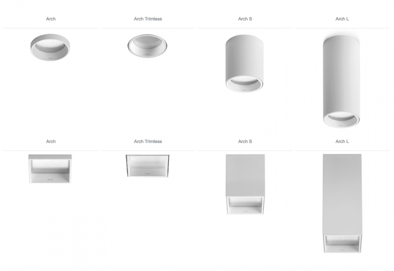
The interior lighting will be indirect on a basis of switched plug sockets in the living room, areas and bedrooms, with LED projectors being installed in the dining room and kitchen units with integrated power by FLUVIA, POINT MINI model, in white on a three-phase electrified rail from the same brand. In the transit areas and bathrooms, high-efficiency pivotable square LED downlights by FLUVIA, ARCH TRIMLESS model, in white will be installed in the false ceiling.
The mechanisms will generally be by SIMON, 100 model, in brilliant white or similar, and the plug sockets in the living room and bedrooms will have USB plugs.
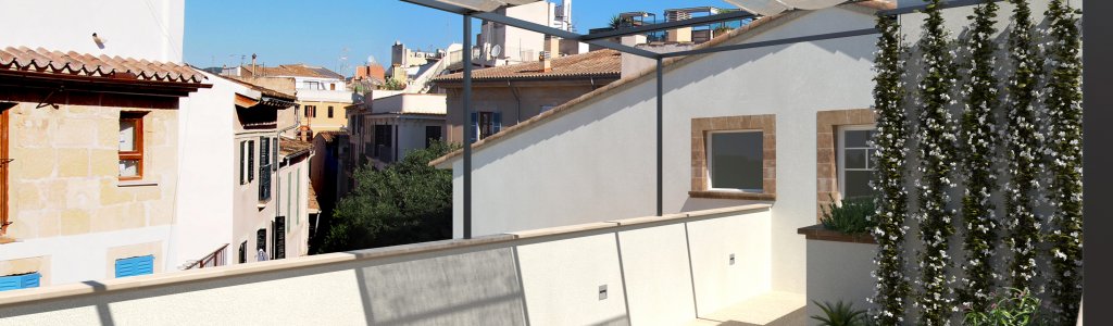
SIMON 100 catalogue Exterior lighting. Terraces and porchs.

Lower floor Floors 1 and 2 Attic
There will be a home automation system in all homes to set controls for lighting, air conditioning and heating. Each home will have a general control screen in the living room (ZENIO brand, Z41 PRO model) and touchscreens in each bedroom to control the underfloor heating (SCHNEIDER Electric brand, MULTITUCH KNX PRO model).
Load estimate as per ITC-BT-10.
The section for these conductors has been calculated taking into account the maximum voltage download from the meter in the general switchboard not being above 1% and the tube sizes will enable the conductor section to be extended by 50%.
The low voltage system is designed and calculated for proper operation as per the requirements of the proposed building.
The safety and protection measures set out in the REBT are fulfilled in the project.
The entire proposed building has appropriate means for supplying the right electricity load as per the needs of each premises.
In terms of energy efficiency, the project has taken into account what is set out in DB-HE; the proposed building has appropriate lighting systems in the communal areas for the needs of users and, in turn, they are energy efficient with a control system that enables switch-on to be adjusted to the real occupancy in the area, as well as a regulation system that optimises use of natural light in areas that meet certain conditions. In this way, the necessary rational energy is achieved for appropriate use of the building.
As per section 3.1.2 in HS3. The kitchens, dining rooms, bedrooms and living rooms should have a supplementary natural ventilation system. They will, therefore, have exterior windows that open or an exterior door.
The homes will have a general mechanical ventilation system. This will be an extraction set by SOLER I PALOU, OZEO model, or similar.
In order to ensure air circulation from dry to wet rooms, the work will be carried out as per the following criteria:
External joinery will be class 0 or 1 as per regulation UNE EN 12207:2000.
This joinery will use the opening joints as inlet openings. The inlet openings connect directly to the outside.
The kitchens will have an additional specific ventilation system with mechanical extraction for steam and odours from cooking. For this, there will be an extractor connected to a separate extraction conduit to those of the general ventilation system in the home, which cannot be used to extract air from rooms with another use with an outflow onto the roof of the building.
The utility rooms will have a certified metal smoke extraction conduit for each heat source with an outflow to the exterior, exceeding the ridge by 1 m in height to channel fuel fumes caused by the heaters to the roof. The chimney will be fully separate from the structural elements and building walls, being attached through brackets, to enable free expansion of the chimney on its route inside the building in hermetically sealed spaces with regard to rooms and with walls that have RF120 fire resistance and sound-proofing at 40 DB. The horizontal route will be as short as possible and easy-to-access to help cleaning and have a condensed soot and rainwater collection zone.
The ventilation in the garage will be natural and to achieve this, an open parking garage has been taken into account with openings that are permanently exposed to the outside and not under 1/20 of the surface area set between two opposing walls, as per CTE-DB-SI; a separate conduit for natural ventilation to extract smoke at a ratio of 0.50 m² per 200 m² of parking floor that expels onto the building roof has been planned in compliance with the General Land Use Plan [PGOU] of Palma.
The proposed air conditioning will be as following:
Lower floor Floors 1, 2 & 3 Attic
Underfloor heating Lower floor Underfloor heating Floor 1 Underfloor heating Floor 2 Underfloor heating Floor 3
The fuel will be natural gas as there is a direct connection to the current network.
The network will only be powered by natural gas to produce domestic hot water in the boilers in each home.
The estimated general consumption is:
Heating and domestic hot water boiler: 24 KW/home, 60 KW in total.
There is a connection that will supply a set of meters comprising four private meters for the homes.
The system begins at a connection to be carried out by the utility company from the medium pressure mains (MOP4) with a guaranteed minimum relative supply pressure of 100 kPa (1kg/cm²) and a maximum pressure of 400 kPa (4 kg/cm²). The company connection will run to the general customer shut-off valve, installed in a recordable tank. A built-in distribution system will run from the tank to the regulation and measuring station for natural gas located in the car park on the ground floor of the building.
The material used for the built-in connection pipes will be medium density polyethylene as per regulation UNE-EN 1555-2, specifically for built-in gas systems.
The general connection will flow to the regulation station and set of meters located in the car park on the ground floor of the building and here, each meter will flow at low pressure to the boiler in each of the homes.
Outside the entry to each home, and inside, certified general shut-off valves will be installed to cut off the gas supply.
Vertical piping will be installed from the utility room entry valve to the equipment to power, where vertical downpipes will be installed for each branch to connect; each piece of equipment will have an individual shut-off.
Copper pipes are proposed for individual connections to gas consumption elements. These pipes will be copper, as per regulation ENE-EN 1057, with a minimum thickness of 1 mm; the pipes will be hard and the accessories will be in the same material with soldered capillary joints.
All valves and accessories used for the system shall comply with regulation UNE 60.708 and must be certified by the utility company.
All piping in the overhead system running inside the building and non-ventilated areas will be protected by a cover with end-point ventilation. The cover will have a minimum interior diameter exceeding by 1 cm the exterior diameter of the protected pipe. The cover will be a black steel pipe with soldering UNE 19.045, with the minimum thickness as per UNE 19.040, with soldered accessories, an exterior finish with two coats of anti-rust paint and two coats of standard colour fire-proof paint. When going through the building walls, the bushing will have an interior diameter 20 mm above the piping diameter, filled with fireproof putty.
The boiler room has an installed power capacity below 70 KW, meaning the requirements of regulation UNE 60.061 do not apply.
The installed boilers will be sealed combustion with a conduit for smoke and gas extraction to the roof of the building, with the section recommended by the equipment manufacturer.
Manual extinguishers are deemed the basic element for first-line defence against fires that may occur in the building. For this reason, manual portable extinguishers shall be distributed so that there is never more than 15 m distance from one of the them on each floor. In open spaces, an extinguisher will be placed for every 300 square meters or surface area fraction, and in car parks with 20 spaces maximum.
In special risk areas or spaces, at least one extinguisher will be located outside and near to the entry door; in addition, those required will be placed inside the space or area so that:
The extinguishers will be placed in highly accessible spots, particularly in the horizontal evacuation routes next to fire hydrants equipped to unify the protection scenario, and the upper part of the extinguisher will be set at a maximum 1.70 m high.
The selected extinguisher agent will mainly be ABC dry chemical anti-reigniting, except in areas with a risk of electrical fire where it will be carbon dioxide.
The extinguishers will be certified as per pressure device regulations (MIRAP5) and UNE 23.110, with their effectiveness shown on the outside and equipped with a hose, directional nozzle and a manual extinguisher agent shut-off device.
The extinguishers will have the following minimum effectiveness:
There will be an MP brand lift, MPGO!EVOLUTION480ST2 model, with incorporated machinery, four stops and access from the communal area on all floors, sound-proofing, with an emergency brake system for downward cable failure, permanent two-way 24h communication with the manufacturer helpline and cage overload control, T2 telescopic doors or similar, in accordance with the manufacturer's documentation, with the first stop on the ground floor and last stop on the third floor. The cage will comply with what is set out in Decree 20/2003 of 28th February 2003, in Law 3/93 on Accessibility and Removal of Architectural Barriers in the Autonomous Region of the Balearic Islands, so that those with reduced mobility and communication can access and travel in the building, have a lacquer door finish and an interior finish in stainless steel with a 1/2 mirror and a single-piece limestone floor.
Lift catalog MpGO!Evolution MP Lift Cabin finishes catalog Lift installation plans
A four-space semi-automatic car lift shall be located on the ground floor with direct street access, designed by IPS Integral Park Systems, Parklift 450-190/340 model. The entry to the garage will be a folding motorised door.
The telecommunications system is in line with Royal Decree-Law 1/1998 of 27th February that sets the bases for the legal implementation of regulations governing Common Telecommunications Infrastructures for Access to Telecommunications Services inside Buildings and Telecommunications Equipment and Systems Installation.
The Common Telecommunications Infrastructures shall include the necessary elements to establish three basic networks that respectively ensure access to:
The telecommunications system in the building will follow the 'Minimum Technical Specifications for Buildings regarding Telecommunications', locating and sizing enclosures, hollows and wiring for common telecommunications infrastructure in buildings, all of which is explained and developed in the specific project.
Below is a complete gallery of project plans for you to explore freely. If you have any questions, please let us know.
Find below a link to our leaflet in PDF format where you can find all the floor plans